AquaMatic/AqMatic Valves, Controlers, Stagers and Ejectors


Call Now


Stager Controllers Documentation

962 AquaMatic Stager Control

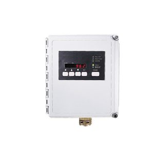
AquaMatic 962 stager control provides an easily adaptable control of stagers for diaphragm valve nests. This fully programmable series of controls provide the ability to fine tune the operation to meet application requirements.

This product is manufactured in the United States of foreign and domestic parts.
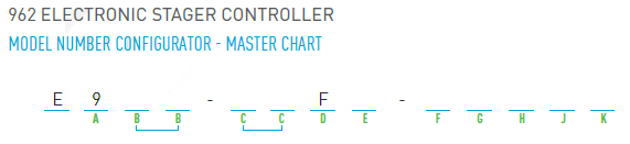
Features & Benefits

  • Electronic Stager Control provide sophisticated electronic controls and reliable performance of the AquaMatic Stagers
  • Accepts an input from a variety of flow sensors to electronically monitor the amount of water used
  • Homing operation – the control and stager automatically synchronize to the service position
  • NEMA 4XFG fiberglass enclosure
  • 115VAC 50/60Hz and 230VAC 50/60Hz
  • Up to 15 programmable timed regeneration cycle are available

Accessories & Options

  • Optional Relay Output during regeneration
  • Optional battery back-up for flow monitoring during power outage
  • Auxiliary switch for electrical output during regeneration cycle(s)

A. Controller

ELECTRONIC CONTROLLER SERIES TO BE PROVIDED
9 = 962 (Battery backup capable)

B. Stager

ROTARY PILOT STAGER SERIES TO BE PROVIDED
48 = 6 Port (brass)
51 = 8 Port (brass)
58 = 16 Port (PVC)

C. Program

STAGER PROGRAM TO BE PROVIDED
00-991 = Standard
SS2 = Special per drawing indicated
TA = Twin alternating softener
(w/service lights on front panel)
TB3 = Twin alternating softener
(w/timed brine pos. & switch output)
-or- Twin alternating filter
skipping steps 2, 3, 7 & 8
TR3 = Twin alternating softener
(w/timed refill pos. & switch output
1 Two character designation from standard stager drawing
2 Special Drawing number placed in last 5 digits of product number
3 Tank In Service is indicated via the 6-digit display of the 962 controller

D. Enclosure

NEMA RATING OF PANEL & ENCLOSURE TO BE PROVIDED
F = NEMA 4X fiberglass panel & enclosure

E. Electrical

POWER REQUIRED TO OPERATE DEVICE
(field configurable)
1 = 115 Volts/50 or 60 Hz
2 = 220 Volts/50 or 60 Hz

F. 1st Aux. Switch

FIRST EXTRA SWITCH TO BE PROVIDED ON ROTARY STAGER
(unless special drawing number is assigned)
S = Service return (homing) (not for58-TA stagers)
W =Status lights cam (58-TA stagers only)

G. 2nd Aux. Switch

SECOND EXTRA SWITCH TO BE PROVIDED ON ROTARY STAGER
(unless special drawing number is assigned)
0 = None (not valid for 58-TA or -TB stagers)
A1 to R = Cam position switch is to be active (I & O not used)
S2 = Service return (homing) (58-TA stagers only)
T = Time switch output (for 58-TA or -TB stagers only)
1 Use letter to indicate cam position, not a number
2 Option “S” standard on 58 stagers w/TA program only

H. Pressure

PROGRAM OF STAGER
(unless special drawing number is assigned)
0 = Standard (vent to open)
1 = Inverted (pressure to open)

J. Relay Output Option

Provides additional relay output during regeneration
(Unless special drawing number is assigned)
0 = None
R = Relay Output Option
(provides a dry or powered set of contacts during service/regeneration)
SPDT
Coil: 12VAC
Contacts: 15A/120VAC/28VDC, 10A/240VAC
Relay also sold as kit 1077737. Includes (1) relay, (1) socket & mounting hardware

K. Stager Revision

(Unless special drawing number is assigned)
B = 48 and 51 series stagers
C = 58 series stagers

REQUEST A QUOTE